TV Content Based Backlight
By Daniel Foote on
Quite a while ago someone told me about the Ambilight system that was incorporated into certain TVs. I was intrigued by the concept, and wondered if it would catch on.
Whilst it didn't seem to catch on in too many consumer TV sets, it did seem to catch on with DIYers in general. I've seen quite a few different types around the place, and most of them involve quite a bit of wiring to get enough resolution around the TV edges. The extensive wiring turned me off, as it's a lot of work to put together and maintain, let alone if you need to move the TV around.
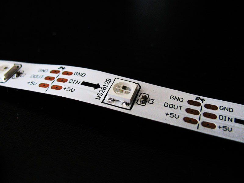
But just a few months ago I came across the WS2812 family of RGB LEDs. These nifty little devices allow you to chain a series of them with just a single input to drive them. They also have a constant current source inside each chip, meaning that the colours and brightness are more stable across a series of these chips - anyone who's bought cheap 12V LED strips off various internet sites will know that the LEDs can vary quite a bit.
I first saw them on Adafruit's web store. They'd already written an Arduino library, and written up how to use them properly, especially with their very tight timing requirements to send data to them. I certainly applaud Adafruit for making their library public, and I feel bad that it's significantly more expensive to source parts through them or a reseller, as I live in Australia.
A few weeks after seeing them in Adafruit's store, I randomly happened to search for them to see where else I could get them from, and stumbled across an eBay listing, which offered a 5 metre strip for $60 (with 30 LEDs per metre), from a seller in Hong Kong. Having ordered items from overseas on many occasions, I was used to the 4 or so week lead time on items from Hong Kong. I ordered it just to see what would happen.
Whilst it was coming, I realised that I could use the strip to build my own version of an Ambilight, something that I'd been keen to try for some time.
Capturing the Screen
A problem that anyone who builds an Ambilight system runs into is how to actually figure out what colours to show for each region of the screen.
In an ideal world, you would put something inline with the HDMI input to the TV (especially if you already have a home theatre receiver doing the HDMI switching for you), and it would pick colours for you and use them. In practice, this isn't so easy. To start with, HDMI is a high bandwidth bus - you need specialised chips and probably a FPGA to process that data. And if that wasn't enough - there is HDCP, meaning that the signal is encrypted between the two.
One of the best systems that I've seen used a HDMI splitter, then an HDMI to S-Video converter, and finally a microprocessor that reads the S-Video to sample the colours for the display. This is a good approach, but it's higher cost than I would like - and if you don't get a suitable HDMI splitter, you lose HDCP, and finally, there is an analog component to the system.
I'll continue to research some simple way to read in HDMI data (and see about the DMCA issues with that too).
In the meantime, that leaves screencapture as the only other way to get the data. This also restricts input sources to be computers, unfortunately, but it's the cheapest way to get everything to work together.
Parts List
The following parts were what I ended up using for my system.
- Arduino Uno R3
- Wiznet based Arduino Ethernet shield
- 5 metre long WS2812 LED strip
- Molex connector
- Hookup wire
Hardware - LEDS
I'm very fortunate to have a Sharp 70" TV that I acquired when I moved into my new house in February 2013. After a month or so, I wall mounted it to give me more options with the other equipment in the theatre.
Most Ambilight systems are fitted to smaller TVs. So when you actually do the measurements of the actual edge of the LCD panel, you end up with just short of 5 metres.
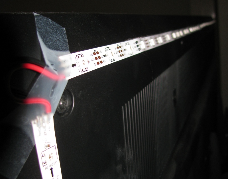
After measuring the LCD panel, and rounding to the nearest LED cut point on the strip, I cut the LED strip and soldered each end together. For where I have the hardware, I started at the bottom left corner, went right, then up, then left and finally down again. With 30 LEDs/metre, I ended up with 46 LEDs across, and 26 LEDs high. (Or 144 channels if you wanted to think of it that way).
The LED strip that I bought conveniently has a 3M branded peel off sticky back. So, with the assistance of a friend, we simply stuck the LED strip to the edges of the back of the TV in the order I had decided.
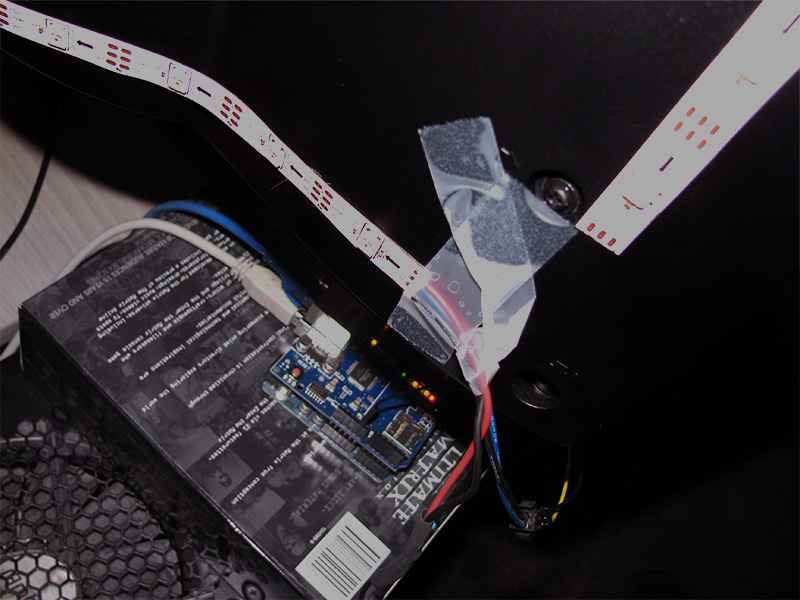
The only remaining connections were for 5V power, and the single data input wire for the Arduino. For power, I temporarily soldered on a molex connector and powered it from a desktop computer that I have in the theatre.
Hardware - driver
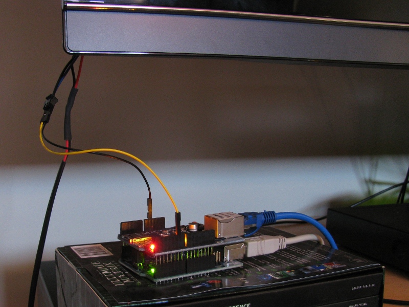
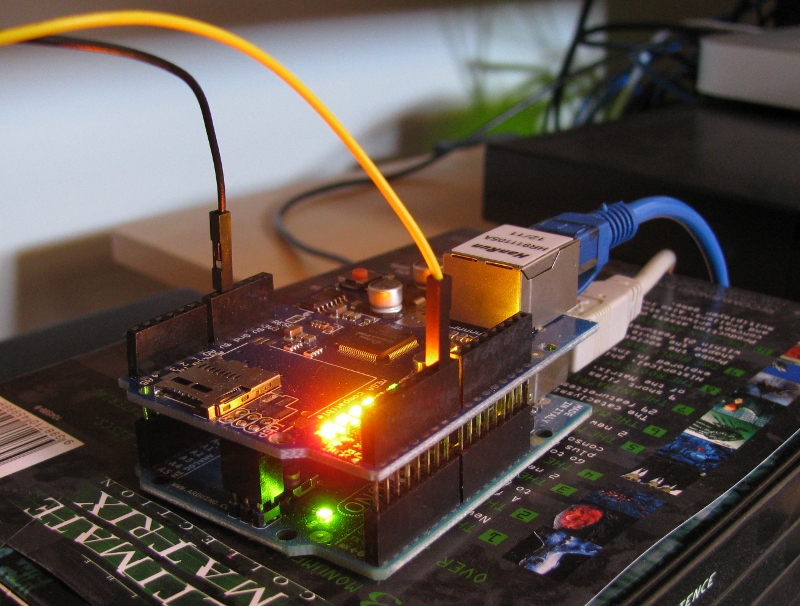
To drive the system, I used an Arduino Uno R3 that I had sitting around the place. I also had an ethernet shield spare, which turned out to be an excellent addition.
The hardware side is very simple. Attach ethernet shield to Arduino, and then plug in the ground and driver pin for the LED strip. The Arduino is currently powered via USB off the desktop computer in the theatre.
Firmware - Arduino
The Arduino sketch is pretty simple. It revolves around two different types of UDP packets sent to it via the network.
The first packet type is just 6 bytes long, and is an input select packet. It contains a magic constant to indicate what it is, and then another byte to select what input, and finally four more bytes that are the colour to set the entire strip to.
The second packet type is up to 606 bytes long in my sketch. To make it longer, you'll have to modify the sketch. This packet contains the magic byte to indicate it contains pixel data, then another byte to say what input it's for. If the input byte doesn't match the current input (set with the input packet type), the rest of it is ignored. If it does match, the next two bytes indicate how many pixels follow. After that is the pixels, 32 bits each. All of these multi byte values are assumed to be in the correct byte order for AVR microcontrollers (little endian). You'll see later the computer software changes the byte order before the packets even leave the computer, to save trying to wangle byte orders on the Arduino itself.
When the Arduino gets a pixel packet, it just writes the pixels out onto the strip directly. It doesn't do anything special for synchronisation.
The sketch I used is checked into the tv-backlight repository on Github.
Sofware - The prototype
My initial temporary target platform was Windows. I had a movie day planned a week ahead, and had chosen Windows as the playback platform for a few reasons relating to the performance of my home network. It's a long story.
Anyway, I knew I was going to have to delve into some deep graphics related code, and graphics coding is one of my weak points. So, purely to get it working, I wrote a Python script on my Linux desktop to prototype it. I ended up using GTK, thinking that it would allow me to test the prototype on Windows as well, and even OSX.
The Python script grabbed the screen, calculated the edge pixels, and sent off the UDP packet, and then repeated this forever.
To calculate the edge pixels, I cheated somewhat. After taking the screenshot (at 1920x1080), I resized it down to the number of pixels on the TV (46x26), which dropped back to some nice fast C code. The resize took less than a millisecond to complete. I used the nearest interpolation method so it would choose hard values for each pixel, rather than trying to smooth them with the adjacent pixels. After it was resized, it's a lot more feasible to scan the edges with Python.
Python also contains the super helpful struct library, which made it trivially easy to take the colours and convert them into binary data (with the appropriate byte order) for the UDP packets.
On my Linux machine, Ubuntu 12.04 with compositing turned on, the GTK screen capture took about 350ms. The rest of the processing and UDP sending accounted for another 5ms or so. So the prototype worked, and worked accurately, but it wasn't fast enough.
The scripts I used are checked into the tv-backlight repository on Github.
Software - Windows
For kicks, I decided to install Python 2.7, PyGTK, and Scipy on my Windows desktop to see how that did. Predictably, it was capturing frames in 2.7 seconds, and then completing the processing in another few milliseconds. So I asked a friend who is much more conversant in graphics programming about a better way to capture frames in Windows 7. The short answer was "this is a rabbit hole". His only suggestion was to disable Aero and see if that helped.
So disable Aero I did. Suddenly, my Python script was capturing frames at 40FPS - including a 1080p video in VLC - and passing that long to the LED strip. In realtime, the effect was quite spectacular and exactly what I had been trying to build!
With some more tweaking - specifically to average several frames together to stop instant changes in the scene causing flashing, and code to detect the black bars in theatrical style widescreen videos, the system was production ready for a Lord of the Rings marathon. 12 hours of 1080p video later, and neither the computer nor the Arduino showed any signs of stopping.
Interestingly enough, I later tried to run the Python script on my Linux laptop, which is fitted with an Intel HD3000 graphics chipset. With compositing turned on, it was capturing at upwards of 80 frames per second.
Some other testing revealed that the script isn't able to capture DirectX surfaces. Some games that I tried did work with quirks, and other games just came up black to the script. To fix this properly, I suspect something using DirectX (or even something lower level) will be required to get it to work.
Sofware - OSX
My primary media centre is a Mac Mini running Plex. So having it working great on a Windows machine wasn't that useful to me. However, the Python script didn't want to work on the Mac, and my simple attempts to install PyGTK on the Mac resulted in something weird that didn't work...
A little bit of Googling showed that OSX ships with Python Objective C bindings, which allow access to core graphics. After some copy and pasting of examples from StackOverflow, I had my script updated to capture images and process them. CoreGraphics was a lot lower level than I expected, so rather than trying to figure out how to get it to composite the average image like the PyGTK one does, I hacked together a simple numerical averaging algorithm to compare frames.
On OSX, the end result is a Python script that can capture and send frames anywhere from 40 to 70 frames per second. The net result is a very nice ambilight system for my media centre.
Switching inputs
When I built my home theatre setup in February 2013, I was pleasantly surprised that basically everything was IP controllable. The only item that wasn't IP controllable was my cheapy DealExtreme LED strip lighting, which required IR signals. I had a spare iTach IR gateway, so everything became IP controllable.
Rather than toting three remotes to control everything, I wrote a simple Python web application, affectionately called Theaterizr, which I access through my Android phone. It's also accessable via my partner's iPhone too, which was the reason for making it a web app. This web app is organised into scenes, and as you enter each scene, it sends the appropriate IP commands to the devices to configure them correctly - much easier for my partner to use than juggling three remote controls!
Because I have this web application already, I can hook it to send input switch commands to my Arduino. This means I can have the ambilight script running all the time on the Windows desktop and the Mac desktop, and the Arduino will simply ignore any packets that don't match it's input.
Quirks and limitations
The first quirk is that the WS2812 LEDs are very, very bright. In fact, they were too bright and drowned out the TV when I first set them up. To get around this, the script divides the colour values by two to half their brightness. This obviously isn't colour correct, but worked well enough for my setup.
The other quirk was the colour definition. Yellows and Reds show up fantastically and match the screen colours almost exactly. Greens are close to the screens colours, but not exact. And blue seems to be quite different from what's on the screen. I don't really know much about colour and colour systems, but I suspect the difference is for two reasons. The first being that I adjusted the TV with the help of a friend to make the colours work better on my TV set. The second reason is that the wall colour isn't white. It's a Dulux colour called "Buff It" which probably interferes with the blue mostly.
Enhancements to come
There are still a few enhancements to be made to this system. But they are relatively minor:
- Neaten up the connection to the TV. It shouldn't be visible from the front, and I plan to affix the Arduino to the TV somehow and route the connections along with the other cabling for the TV.
- Replace the power supply with a standalone one. Currently, the desktop computer has to be on to power the strip. I've ordered seperate 5A power supplies, and I just need to hook them up instead. The only quirk is that the 5M strip, at full white brightness, is rated for about 10A.
Building your own
If you would like to build your own system, here are a few notes about the code and system that I've published:
- You can affix the LED strips in any order to your TV. If you use a different order to mine, you'll need to update your script to send the pixels in the correct order. You should be able to see in the code where this is, and it would just be a matter of rearranging the order of the for loops to achieve this.
- Power supply. The 5M WS2812 strip is rated to draw about 10 amps at full brightness. Make sure you have a suitable power supply to back it up. A standalone computer power supply, regardless of it's rating, should be suitable to power the strip. If you're using a power supply that's in a computer, check to make sure you have enough margin to run the LED strip on it.
- Network. Don't forget to update the IP addresses (and possibly MAC address) in the Arduino sketch, so it matches your network environment.